Beberapa macam Utility untuk Troubleshooting koneksi Jaringan TCP/IP pada suatu jaringan koneksi internet atau jaringan koneksi internetwork
Dalam suatu infrastructure jaringan yang berskala besar dalam suatu organisasi, kemampuan untuk melakukan suatu troubleshooting masalah jaringan dan juga masalah system adalah sangat penting. Masalah dalam suatu jaringan adalah kebanyakan masalah konesi kepada jaringan. Strategy dasar untuk troubleshooting koneksi jaringan adalah berangkat dari sumber masalah / lokasi masalah, dan kita bisa memulai memferifikasi fungsional pada layer-layer jaringan bagian bawah. Jika sebuah komputer mengalami masalah koneksi kepada jaringan local langkah pertama yang bisa kita lakukan adalah memeriksa konfigurasi TCP/IP meliputi IP address, subnet mask, gateway, atau parameter IP lainnya.
- Untuk troubleshooting konfigurasi jaringan gunakan tool berikut: ipconfig, network diagnostic, dan Netdiag
- Untuk troubleshooting masalah koneksi gunakan tool berikut: ping, pathping, tracert, dan juga arp
Troubleshooting konfigurasi TCP/IP
Misalkan konfigurasi sederhana pada diagram jaringan berikut ini adalah diagram umum untuk jaringan internet di rumahan untuk koneksi ke Internet. Jika anda menggunakan layanan Speedy Telkom, maka modem-router yang digunakan biasanya mempunyai konfigurasi default dengan IP address 192.168.1.1 yang mana IP address ini merupakan IP address Gateway bagi komputer yang terhubung dengan jaringan. Modem-router yang dipakai biasanya juga berfungsi sebagai DHCP server yang memberikan konfigurasi IP address kepada komputer dalam jaringan. Misalkan pada komputer A ada masalah tidak bisa koneksi terhadap komputer B atau tidak bisa koneksi ke Internet.

Troubleshooting Koneksi Internet
Untuk troubleshooting konfigurasi TCP/IP maka kita bisa memulai dari komputer yang bermasalah. Kita bisa memeriksa konfigurasi TCP/IP dengan menggunakan tool ipconfig pada command prompt. Bagaimana caranya? Tekan tombol ‘Windows’ dan tombol ‘R’ secara bersamaan untuk memunculkan windows RUN berikut dan ketik “cmd” terus klik “OK”.
Setelah itu pada command prompt ketik ipconfig, dan akan muncul konfigurasi IP address, subnet mask, dan gateway. Atau jika ingin melihat konfigurasi lebih lengkap gunakan parameter /all menjadi ipconfig /all dan tekan Enter, maka akan muncul konfigurasi lengkap seperti gambar dibawah ini dan kita bisa melihat konfigurasi DNS server yang dipakai (pada contoh terlihat DNS server dari Telkom).

Troubleshooting Dg ipconfig /all
Misalkan terjadi IP address duplikat dengan komputer lain yang ada pada jaringan maka pada subnet mask akan muncul: 0.0.0.0. kemungkinan terjadi IP duplikat jika anda tidak menggunakan DHCP server, dan IP address di setup manual ke komputer-2. Untuk memastikan bahwa konfigurasi TCP/IP pada komputer anda benar, maka gunakan ping loopback dengan mengetikkan di command promp ping 127.0.0.1 atau ping localhost, dan jika konfigurasi sudah benar maka akan muncul respon dengan “0% lost” seperti pada gambar berikut ini.

Troubleshooting Koneksi - Ping Localhost
Jika semua tampak bagus tapi anda masih tidak bisa juga akses ke internet Speedy, cobalah ping ke computer satunya dengan mengetikkan command berikut ke IP address computer B, ping 192.168.1.5. jika respon nya juga tidak bagus dengan 0% lost, maka perhatikan lampu di modem-router apakah lampu ADSL dan Internet juga nyala normal, bisa jadi lampu Internet mati, berarti ada masalah dengan Speedy. Hal ini bisa saja terjadi jika anda mengubah password account anda di website nya Telkom Speedy dengan password yang anda gampang mengingatnya.
Jika anda mengubah password account anda di Website Telkom Speedy, maka anda juga harus mengubah password yang ada di modem-router di rumah anda, anda bisa menelpon 147 untuk minta bantuan – setidaknya dipandu untuk mengganti password di modem-router anda.
Network Diagnostic
Dalam suatu infrastructure jaringan windows server 2003, network diagnostic biasa digunakan untuk untuk troubleshooting jaringan juga. Network Diagnostic dalah interface grafis yang sudah ada dalam Windows server 2003 yang bisa memberikan informasi detail tentang konfigurasi jaringan local. Untuk mengaksesnya, jalankan Help and Support dari Start Menu => Tools pada Support Task area => klik Tools => cari Network Diagnostics dan klik => akan muncul disisi kanan seperti pada gambar dibawah berikut ini.

Network Diagnostic - Scan
Ketika “Scan Your System” di klik, Network Dianostic akan menjalankan serangkaian test yang akan mengumpulkan informasi tentang environment local seperti gambar berikut ini.

Network Diagnostic - Hasil Scan
Informasi yang dikumpulkan akan dijabarkan dalam serangkainan category yang secara default ada tiga katagory:
- Internet service category, meliputi informasi tentang Outlook Express Mail, Microsoft Outlook Express News, dan konfigurasi Internet Explorer Web Proxy
- Category informasi komputer, meliputi setting parameter Registry, Operating system dan versinya
- Category Modem and Network Adapter, meliputi setting parameter registry modem, network adapter dan network clients.
NETDIAG Utility
Netdiag adalah utility command line yang harus dinstall terlebih dahulu dari CD instalasi Windows server 2003 yang berada pada directory \Support\Tools dan dobel klik file Supports.msi.
Untuk melakukan troubleshooting masalah jaringan, anda bisa melakukan scan Netdiag dan periksa hasilnya atas error message yang mungkin ada.
Troubleshooting Koneksi menggunakan Ping dan Pathping
Ping adalah utilitas untuk memeriksa koneksi level IP, sementara Pathping digunakan untuk mendeteksi kehilangan paket saat paket menjelajah dari hop ke hop (dari router ke router). Command Ping digunakan untuk mengirim permintaan echo ICMP (Internet Control Message Protocol) kepada host yang di target seperti pada contoh diatas.
- Untuk verifikasi konfigurasi TCP/IP gunakan ping 127.0.0.1 pada command prompt. Jika test ping gagal atau tidak ada response (100% lost) maka bisa jadi driver tidak benar, network adapternya rusak, atau terjadi interferensi IP dengan service lain.
- Untuk verifikasi IP address sudah benar ditambahkan ke komputer lakukan ping ke IP address local host pada command prompt
- Secara umum gunakan ping dengan IP address atau host name. jika ping dengan IP address sukses, bisa jadi ping ke hostname gagal dikarenakan masalah name resolution
Jika usaha ping gagal di setiap titik, periksa yang berikut
- Pastikan bahwa IP address local komputer dan juga subnet mask sudah dikonfigure dengan benar
- Default gateway juga dikonfigure dengan benar dan link antara local host dan gateway juga sudah dikonfigure dengan benar.
Jika ping ke remote host pada link yang lambat seperti sambungan link satellite, maka response akan memakan waktu agak lambat untuk merespon. Gunakan parameter –w untuk respon time-out yang agak lama misal 10000 msec gunakan “ping –w 10000 IP_Address”. Default time-out dari ping adalah 1000 msec (1 detik).
Troubleshooting dengan Tracert
Tracert adalah utility untuk tracing route yang bisa anda gunakan untuk tracking path sampai 30 hops router-to-router. tracert juga menggunakan ICMP echo request kepada suatu IP address, dengan menaikkan TTL (time to live) pada header IP dimulai dari 1, dan menganalisa error ICMP saat respon kembalian. Misal pada contoh berikut dilakukan tracert yahoo.com dari local komputer.
Jika ingin mendapatkan link yang sering tersendat-sendat gunakan pathping untuk melihat disisi router mana terjadinga delay / kehilangan paket yang sangat besar.
Troubleshooting menggunakan utility ARP
Jika anda bisa melakukan ping pada kedua IP address local anda dan juga loopback dengan sukses, akan tetapi anda tidak bisa ping ke suatu host pada subnet local, maka periksalah cache ARP (Address Resolution Protocol) barangkali ada kesalahan / error. Utility ARP ini sangat berguna untuk melihat cache daftar ARP, gunakan arp –a pada local host. Untuk membersihkan daftar arp, gunakan parameter –d, arp –d IP_address.
Untuk melihat address physical (MAC address) gunakan ipconfig /all atau getmac. Jika anda tidak mendapatkan error pada command ARP –a dan anda juga tidak berhasil ping ke host pada subnet yang sama, maka anda bisa memeriksa pada media fisik seperti LAN Card, Switch, dan atau cable jaringan.
Semoga bermanfa’at, salam.
http://www.sysneta.com/troubleshooting-koneksi-internettrouble shooting dalam TCP/IP
Troubleshooting TCP/IP
The sections in this chapter describe common features of TCP/IP and provide solutions to some of the most common TCP/IP problems. The following items will be covered:
•![]() TCP/IP Introduction
TCP/IP Introduction
•![]() Tools for Troubleshooting IP Problems
Tools for Troubleshooting IP Problems
•![]() General IP Troubleshooting Theory and Suggestions
General IP Troubleshooting Theory and Suggestions
•![]() Troubleshooting Basic IP Connectivity
Troubleshooting Basic IP Connectivity
•![]() Troubleshooting Physical Connectivity Problems
Troubleshooting Physical Connectivity Problems
•![]() Troubleshooting Layer 3 Problems
Troubleshooting Layer 3 Problems
•![]() Troubleshooting Hot Standby Router Protocol (HSRP)
Troubleshooting Hot Standby Router Protocol (HSRP)
TCP/IP Introduction
In the mid-1970s, the Defense Advanced Research Projects Agency (DARPA) became interested in establishing a packet-switched network to provide communications between research institutions in the United States. DARPA and other government organizations understood the potential of packet-switched technology and were just beginning to face the problem that virtually all companies with networks now have—communication between dissimilar computer systems.
With the goal of heterogeneous connectivity in mind, DARPA funded research by Stanford University and Bolt, Beranek, and Newman (BBN) to create a series of communication protocols. The result of this development effort, completed in the late 1970s, was the Internet Protocol suite, of which the Transmission Control Protocol (TCP) and the Internet Protocol (IP) are the two best-known protocols.
The most widespread implementation of TCP/IP is IPv4 (or IP version 4). In 1995, a new standard, RFC 1883—which addressed some of the problems with IPv4, including address space limitations—was proposed. This new version is called IPv6. Although a lot of work has gone into developing IPv6, no wide-scale deployment has occurred; because of this, IPv6 has been excluded from this text.
Internet Protocols
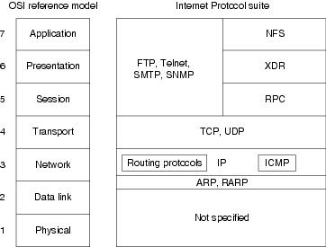
Internet protocols can be used to communicate across any set of interconnected networks. They are equally well suited for local-area network (LAN) and wide-area network (WAN) communications. The Internet suite includes not only lower-layer specifications (such as TCP and IP), but also specifications for such common applications as e-mail, terminal emulation, and file transfer. Figure 7-1 shows some of the most important Internet protocols and their relationships to the OSI reference model.
As an interesting side note, the seven-layer model actually came about after TCP/IP. DARPA used a four-layer model instead, which the OSI later expanded to seven layers. This is why TCP/IP doesn't generally fit all that well into the seven-layer OSI model.
Figure 7-1 The Internet Protocol Suite and the OSI Reference Model
Creation and documentation of the Internet Protocol suite closely resemble an academic research project. The protocols are specified and refined in documents called Requests For Comments (RFCs), which are published, reviewed, and analyzed by the Internet community. Taken together, the RFCs provide a colorful history of the people, companies, and trends that have shaped the development of what is today the world's most popular open-system protocol suite.
The Network Layer
IP is the primary Layer 3 protocol in the TCP/IP suite. IP provides the logical addressing that enables communication across diverse networks. IP also provides fragmentation and reassembly of datagrams and error reporting. Along with TCP, IP represents the heart of the Internet Protocol suite. The IP packet format is shown in Figure 7-2.
Figure 7-2 The IP Packet Format
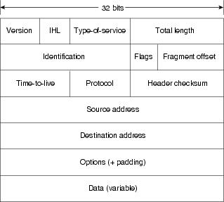
The fields of the IP packet are as follows:
•![]() Version—Indicates the version of this IP datagram.
Version—Indicates the version of this IP datagram.
•![]() IP Header Length (IHL)—Indicates the datagram header length in 32-bit words.
IP Header Length (IHL)—Indicates the datagram header length in 32-bit words.
•![]() Type-of-Service—Specifies how a particular upper-layer protocol would like the current datagram to be handled. Datagrams can be assigned various levels of importance using this field.
Type-of-Service—Specifies how a particular upper-layer protocol would like the current datagram to be handled. Datagrams can be assigned various levels of importance using this field.
Today this field is used primarily to provide quality of service (QoS) capabilities to TCP/IP for applications requiring predictable bandwidth or delay. RFC 2474 describes a method by which the TOS field is replaced by a DS field that is used to provide differentiated services (DiffServ) on networks. This field is split into two parts. The first 6 bits are used for the DSCP codepoint, which is used to differentiate traffic. The last 2 bits, or CU, are ignored by DiffServ-compliant nodes.
•![]() Total Length—Specifies the length of the entire IP packet, including data and header, in bytes.
Total Length—Specifies the length of the entire IP packet, including data and header, in bytes.
•![]() Identification—Consists of an integer identifying this datagram. This field is used to help piece together datagram fragments.
Identification—Consists of an integer identifying this datagram. This field is used to help piece together datagram fragments.
•![]() Flags—Consists of 3 bits, of which the low-order 2 bits control fragmentation. One bit specifies whether the packet can be fragmented; the second bit specifies whether the packet is the last fragment in a series of fragmented packets.
Flags—Consists of 3 bits, of which the low-order 2 bits control fragmentation. One bit specifies whether the packet can be fragmented; the second bit specifies whether the packet is the last fragment in a series of fragmented packets.
•![]() Time-to-Live—Maintains a counter that gradually decrements down to zero, at which point the datagram is discarded. This keeps packets from looping endlessly.
Time-to-Live—Maintains a counter that gradually decrements down to zero, at which point the datagram is discarded. This keeps packets from looping endlessly.
•![]() Protocol—Indicates which upper-layer protocol receives incoming packets after IP processing is complete.
Protocol—Indicates which upper-layer protocol receives incoming packets after IP processing is complete.
•![]() Header Checksum—Helps ensure IP header integrity.
Header Checksum—Helps ensure IP header integrity.
•![]() Source Address—Specifies the sending node.
Source Address—Specifies the sending node.
•![]() Destination Address—Specifies the receiving node.
Destination Address—Specifies the receiving node.
•![]() Options—Allows IP to support various options, such as security.
Options—Allows IP to support various options, such as security.
•![]() Data—Contains upper-layer information.
Data—Contains upper-layer information.
Addressing
As with all network layer protocols, the addressing scheme is integral to the process of routing IP datagrams through an internetwork. An IP address is 32 bits in length, divided into either two or three parts. The first part designates the network address, the second part (if present) designates the subnet address, and the final part designates the host address. Subnet addresses are present only if the network administrator has decided that the network should be divided into subnetworks. The lengths of the network, subnet, and host fields are all variable.
Today's Internet does not segment addresses along classful bounds—it is almost entirely classless. The separation between networks and subnets has been effectively eliminated. The requirement to understand network classes and the difference between a network and a subnet remains solely because of configuration and behavioral issues with network devices.
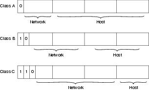
IP addressing supports five different network classes, and the high-order—far-left—bits indicate the network class:
•![]() Class A networks provide 8 bits for the Network Address field. The high-order bit (at far left) is 0.
Class A networks provide 8 bits for the Network Address field. The high-order bit (at far left) is 0.
•![]() Class B networks allocate 16 bits for the Network Address field and 16 bits for the Host Address field. This address class offers a good compromise between network and host address space. The first 2 high-order bits are 10.
Class B networks allocate 16 bits for the Network Address field and 16 bits for the Host Address field. This address class offers a good compromise between network and host address space. The first 2 high-order bits are 10.
•![]() Class C networks allocate 24 bits for the Network Address field. Class C networks provide only 8 bits for the Host field, however, so the number of hosts per network may be a limiting factor. The first 3 high-order bits are 110.
Class C networks allocate 24 bits for the Network Address field. Class C networks provide only 8 bits for the Host field, however, so the number of hosts per network may be a limiting factor. The first 3 high-order bits are 110.
•![]() Class D addresses are reserved for multicast groups, as described formally in RFC 1112. The first 4 high-order bits are 1110.
Class D addresses are reserved for multicast groups, as described formally in RFC 1112. The first 4 high-order bits are 1110.
•![]() Class E addresses are also defined by IP but are reserved for future use. The first 4 high-order bits are 1111.
Class E addresses are also defined by IP but are reserved for future use. The first 4 high-order bits are 1111.
IP addresses are written in dotted decimal format (for example, 34.10.2.1). Figure 7-3 shows the address formats for Class A, B, and C IP networks.
Figure 7-3 Class A, B, and C Address Formats
IP networks can also be divided into smaller units called subnets. Subnets provide extra flexibility for network administrators. For example, assume that a network has been assigned a Class B address, and all the nodes on the network currently conform to a Class B address format. Then assume that the dotted decimal representation of this network's address is 172.16.0.0 (all zeros in the Host field of an address specifies the entire network). Rather than change all the addresses to some other basic network number, the administrator can subdivide the network using subnetting. This is done by borrowing bits from the host portion of the address and using them as a subnet field, as shown in Figure 7-4.
Figure 7-4 Subnet Addresses
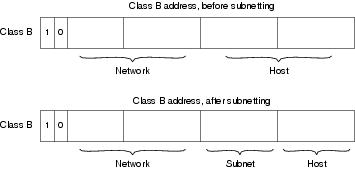
If a network administrator has chosen to use 8 bits of subnetting, the third octet of a Class B IP address provides the subnet number. For example, address 172.16.1.0 refers to network 172.16, subnet 1; address 172.16.2.0 refers to network 172.16, subnet 2; and so on. In today's world, the difference between subnet bits and the natural mask has become blurred, and you will often see only a prefix length that specifies the length of the entire mask (natural mask plus subnet bits). It is still important to understand the difference between the natural network mask, which is determined by the network class, and the subnet mask, because routers sometimes make assumptions based on the natural mask of an address. For example, the natural mask of 10.1.1.1/24 is 8 bits because this is a class A network, even though the subnet mask is 24 bits.
Subnet masks can be expressed in two forms: prefix length (as in /24), or dotted-decimal notation (As in 255.255.255.0). Both forms mean exactly the same thing and can easily be converted to the other, as seen in Example 7-1.
255.255.255.0 = 11111111 11111111 11111111 00000000 = /24 bits (count the |
On some media (such as IEEE 802 LANs), the correlation between media addresses and IP addresses is dynamically discovered through the use of two other members of the Internet Protocol suite: the Address Resolution Protocol (ARP) and the Reverse Address Resolution Protocol (RARP). ARP uses broadcast messages to determine the hardware Media Access Control (MAC)-layer address corresponding to a particular IP address. ARP is sufficiently generic to allow use of IP with virtually any type of underlying media-access mechanism. RARP uses broadcast messages to determine the Internet address associated with a particular hardware address. RARP is particularly important to diskless nodes, which may not know their IP address when they boot.
Internet Routing
Routing devices in the Internet have traditionally been called gateways—an unfortunate term because elsewhere in the industry, the term gateway applies to a device with somewhat different functionality. Gateways (which we will call routers from this point on) within the Internet are organized hierarchically.
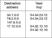
Dynamic routing protocols, such as RIP and OSPF, provide a means by which routers can communicate and share information about routes that they have learned or are connected to. This contrasts with static routing, in which routes are established by the network administrator and do not change unless they are manually altered. An IP routing table consists of destination address/next-hop pairs. A sample entry, shown in Figure 7-5, is interpreted as meaning, "To get to network 34.1.0.0 (subnet 1 on network 34), the next stop is the node at address 54.34.23.12."
Figure 7-5 An Example of an IP Routing Table
IP routing specifies that IP datagrams travel through internetworks one hop at a time; the entire route is not known at the outset of the journey. Instead, at each stop, the next destination is calculated by matching the destination address within the datagram with an entry in the current node's routing table. Each node's involvement in the routing process consists only of forwarding packets based on internal information, regardless of whether the packets get to their final destination. In other words, IP does not provide for error reporting back to the source when routing anomalies occur. This task is left to other Internet protocols, such as the Internet Control Message Protocol (ICMP) and TCP protocol.
http://www.cisco.com/en/US/docs/internetworking/troubleshootin
0 komentar:
Posting Komentar